This link has been bookmarked by 222 people . It was first bookmarked on 29 Jun 2006, by Haakon Leonsson.
-
31 Dec 17
-
16 Mar 15
-
29 Sep 14
-
Static (or structural)
-
Static (or structural)
-
Static (or structural) v
-
Static (or structural) view:
-
-
11 Sep 14
-
24 Aug 14
-
28 Jun 14
-
Superstructure
-
Infrastructure
-
A diagram is a partial graphic representation of a system's model
-
UML models can be exchanged among UML tools by using the XML Metadata Interchange (XMI) interchange format.
-
Structure diagrams
-
Behavior diagrams
-
stereotyping
-
-
22 May 14
-
26 Jan 14
-
15 Jan 14
-
28 Nov 13
-
15 Nov 13
-
UML does not restrict UML element types to a certain diagram type. In general, every UML element may appear on almost all types of diagrams; this flexibility has been partially restricted in UML 2.0.
-
emphasize what must happen in the system being modeled
-
functionality
-
the flow of control and data among the things in the system
-
a subset of behavior diagrams
-

-
-
29 Sep 13
-
08 Sep 13
-
- activities
- actors
- business processes
- database schemas
- (logical) components
- programming language statements
- reusable software components.[3]
Unified Modeling Language (UML) combines techniques from data modeling (entity relationship diagrams), business modeling (work flows), object modeling, and component modeling. It can be used with all processes, throughout the software development life cycle, and across different implementation technologies.[2]
The Unified Modeling Language (UML) offers a standard way to visualize a system's architectural blueprints, including elements such as:
-
Unified Modeling Language (UML) is a standardized (ISO/IEC 19501:2005), general-purpose modeling language in the field of software engineering.
-
- activities
- actors
- business processes
- database schemas
- (logical) components
- programming language statements
- reusable software components.[3]
Unified Modeling Language (UML) combines techniques from data modeling (entity relationship diagrams), business modeling (work flows), object modeling, and component modeling. It can be used with all processes, throughout the software development life cycle, and across different implementation technologies.[2]
The Unified Modeling Language (UML) offers a standard way to visualize a system's architectural blueprints, including elements such as:
-
- Class diagram: describes the structure of a system by showing the system's classes, their attributes, and the relationships among the classes.
- Component diagram: describes how a software system is split up into components and shows the dependencies among these components.
- Composite structure diagram: describes the internal structure of a class and the collaborations that this structure makes possible.
- Deployment diagram: describes the hardware used in system implementations and the execution environments and artifacts deployed on the hardware.
- Object diagram: shows a complete or partial view of the structure of an example modeled system at a specific time.
- Package diagram: describes how a system is split up into logical groupings by showing the dependencies among these groupings.
- Profile diagram: operates at the metamodel level to show stereotypes as classes with the <<stereotype>> stereotype, and profiles as packages with the <<profile>> stereotype. The extension relation (solid line with closed, filled arrowhead) indicates what metamodel element a given stereotype is extending.
Structure diagrams[edit source | editbeta]
Structure diagrams emphasize the things that must be present in the system being modeled. Since structure diagrams represent the structure, they are used extensively in documenting the software architecture of software systems.
-
- Activity diagram: describes the business and operational step-by-step workflows of components in a system. An activity diagram shows the overall flow of control.
- UML state machine diagram: describes the states and state transitions of the system.
- Use Case Diagram: describes the functionality provided by a system in terms of actors, their goals represented as use cases, and any dependencies among those use cases.
Behavior diagrams[edit source | editbeta]
Behavior diagrams emphasize what must happen in the system being modeled. Since behavior diagrams illustrate the behavior of a system, they are used extensively to describe the functionality of software systems.
-
- Communication diagram: shows the interactions between objects or parts in terms of sequenced messages. They represent a combination of information taken from Class, Sequence, and Use Case Diagrams describing both the static structure and dynamic behavior of a system.
- Interaction overview diagram: provides an overview in which the nodes represent communication diagrams.
- Sequence diagram: shows how objects communicate with each other in terms of a sequence of messages. Also indicates the lifespans of objects relative to those messages.
- Timing diagrams: a specific type of interaction diagram where the focus is on timing constraints.
Interaction diagrams[edit source | editbeta]
Interaction diagrams, a subset of behavior diagrams, emphasize the flow of control and data among the things in the system being modeled:
-
Meta modeling[edit source | editbeta]
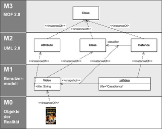 Illustration of the Meta-Object Facility.
 Main article: Meta-Object Facility
The Object Management Group (OMG) has developed a metamodeling architecture to define the Unified Modeling Language (UML), called the Meta-Object Facility (MOF).[16] The Meta-Object Facility is designed as a four-layered architecture, as shown in the image at right. It provides a meta-meta model at the top layer, called the M3 layer. This M3-model is the language used by Meta-Object Facility to build metamodels, called M2-models.
The most prominent example of a Layer 2 Meta-Object Facility model is the UML metamodel, the model that describes the UML itself. These M2-models describe elements of the M1-layer, and thus M1-models. These would be, for example, models written in UML. The last layer is the M0-layer or data layer. It is used to describe runtime instance of the system.
Beyond the M3-model, the Meta-Object Facility describes the means to create and manipulate models and metamodels by defining Common Object Request Broker Architecture (CORBA) interfaces that describe those operations. Because of the similarities between the Meta-Object Facility M0-model and UML structure models, Meta-Object Facility metamodels are usually modeled as UML class diagrams. A supporting standard of the Meta-Object Facility is XMI, which defines an XML-based exchange format for models on the M3-, M2-, or M1-Layer.
-
-
16 Jun 13
-
21 Mar 13
-
In 2000 the Unified Modeling Language was accepted by the International Organization for Standardization (ISO) as industry standard for modeling software-intensive systems.
-
Unified Modeling Language (UML) combines techniques from data modeling (entity relationship diagrams), business modeling (work flows), object modeling, and component modeling
-
- activities
- actors
- business processes
- database schemas
- (logical) components
- programming language statements
- reusable software components.[4]
The Unified Modeling Language (UML) offers a standard way to visualize a system's architectural blueprints, including elements such as:
-
UML aims to be a standard modeling language which can model concurrent and distributed systems.
-
UML has been evolving since the second half of the 1990s
-
A diagram is a partial graphic representation of a system's model. The model also contains documentation that drives the model elements and diagrams (such as written use cases).
-
- Static (or structural) view: emphasizes the static structure of the system using objects, attributes, operations and relationships. The structural view includes class diagrams and composite structure diagrams.
- Dynamic (or behavioral) view: emphasizes the dynamic behavior of the system by showing collaborations among objects and changes to the internal states of objects. This view includes sequence diagrams, activity diagrams and state machine diagrams.
UML diagrams represent two different views of a system model:[14]
-
Interaction diagrams, a subset of behavior diagrams, emphasize the flow of control and data among the things in the system being modeled:
-
-
14 Mar 13
-
16 Feb 13
-
24 Jan 13
-
graphic notation
-
concurrent
-
a standard modeling languag
-
operations
-
Static (or structural) view
-
objects,
-
attributes
-
relationships.
-
Dynamic (or behavioral) view
-
collaborations
-
14 types
-
Structural UML diagrams
-
Behavioral UML diagrams
-
every UML element may appear
-
on almost all types of diagrams
-
r note
-
An activity diagram shows the overall flow of control
-
-
23 Jan 13
-
01 Jan 13
-
13 Dec 12
-
13 Nov 12
-
07 Nov 12
-
03 Nov 12
-
15 Oct 12
-
24 Sep 12
 Biru Yang
Unified Modeling Language (UML) is a standardized general-purpose modeling language in the field of object-oriented software engineering. The standard is managed, and was created, by the Object Management Group. It was first added to the list of OMG adopted technologies in 1997, and has since become the industry standard for modeling software-intensive systems.[1]
-
23 Sep 12
-
02 Sep 12
-
21 Jul 12
-
contains many diagrams and constructs that are redundant or infrequently used.
-
-
24 Apr 12
-
04 Apr 12
-
03 Apr 12
-
05 Mar 12
-
02 Mar 12
-
02 Jan 12
-
Three Amigos
-
Booch method
-
Abstraction Method
-
Static
-
Dynamic
-
19 Nov 11
-
13 Oct 11
-
06 Sep 11
-
07 Jul 11
-
21 Jun 11
-
19 Jun 11
-
25 May 11
-
The Unified Modeling Language (UML) is used to specify, visualize, modify, construct and document the artifacts of an object-oriented software-intensive system under development.[1]
-
-
23 May 11
-
UML is not a development method
-
it was designed to be compatible with the leading object-oriented software development methods of its time
-
new methods have been created based on UML
-
Abstraction Method and Dynamic Systems Development Method.
-
A diagram is a partial graphic representation of a system's mode
-
Static (or structural) view: e
-
Dynamic (or behavioral) view:
-
-
25 Apr 11
-
24 Apr 11
-
a standardized general-purpose modeling language
-
to specify, visualize, modify, construct and document the artifacts of an object-oriented software-intensive syste
-
-
29 Mar 11
-
23 Mar 11
-
03 Mar 11
-
17 Jan 11
-
Unified Modeling Language (UML) is a standardized (ISO/IEC 19501:2005), general-purpose modeling language in the field of software engineering.
-
a set of graphic notation techniques to create visual models of object-oriented software-intensive systems.
-
-
In 2000 the Unified Modeling Language was accepted by the International Organization for Standardization (ISO) as industry standard for modeling software-intensive systems.
-
software engineering
-
The Unified Modeling Language (UML) offers a standard way to visualize a system's architectural blueprints
-
prime examples of unintelligible geekspeak
-
-
05 Jan 11
-
31 Oct 10

-
06 Oct 10
-
12 Sep 10
 dave sgonechina
"Unified Modeling Language (UML) is a standardized general-purpose modeling language in the field of software engineering. The standard is managed, and was created by, the Object Management Group."
-
18 Jul 10
-
13 Jul 10
-
Unified Modeling Language (UML) is a standardized general-purpose modeling language in the field of software engineering.
-
UML includes a set of graphic notation techniques to create visual models of software-intensive systems.
-
UML aims to be a standard modeling language which can model concurrent and distributed systems.
-
-
01 Jun 10
-
16 May 10
-
26 Apr 10
-
24 Feb 10
-
18 Feb 10
-
03 Feb 10
-
19 Jan 10
-
19 Oct 09
-
06 Oct 09
-
19 Aug 09
-
05 Aug 09
-
21 Mar 09
 Dante-Gabryell Monson
Unified Modeling Language (UML) is a standardized general-purpose modeling language in the field of software engineering.
UML includes a set of graphical notation techniques to create abstract models of specific systems.Projects Design software ReferenceMaps Mapping Development programming architecture uml processdimensions arevoir ReQuest tolearn
-
18 Jan 09
-
19 Dec 08
-
17 Dec 08
-
09 Dec 08
-
20 Nov 08

-
19 Nov 08
-
13 Nov 08

-
07 Oct 08
-
24 Sep 08
-
24 Jul 08
-
Structure diagrams emphasize what things must be in the system being modeled:
-
Behavior diagrams emphasize what must happen in the system being modeled:
-
-
- Communication diagram
- Interaction overview diagram (added in UML 2.x)
- Sequence diagram
- Timing diagram (added in UML 2.x)
Interaction diagrams, a subset of behavior diagrams, emphasize the flow of control and data among the things in the system being modeled:
-
-
-
18 Jul 08
-
16 Jul 08
-
Unified Modeling Language
-
-
20 May 08
-
30 Apr 08
-
29 Apr 08
-
Functional requirements
-
Static structural
-
Dynamic behavior
-
XMI interchange format
-
things must be in the system
-
what must happen
-
flow of control and data
-
Only the code is in sync with the code
-
The code is the design
-
All models are wrong, but some models are useful
-
gravitates toward solutions that reside at the intersection
-
particularly pronounced if the implementation language does not adhere to orthodox object-oriented
-
most applicable features of UML must be delimited for use by the design team
-
-
03 Mar 08
-
21 Feb 08
-
27 Sep 07
-
11 Sep 07
 Travis Stiles
In the field of software engineering, the Unified Modeling Language (UML) is a standardized specification language for object modeling. UML is a general-purpose modeling language that includes a graphical notation used to create an abstract model of a sys
uml programming reference development design usecase ux ixd diagrams mapping
-
07 Jul 07
-
06 Jul 07
 Adam Crowe
For structure: Actor, attribute, class, component, interface, object, package. -- For behavior: Activity, event, message, method, operation, state, use case. -- For relationships
Aggregation, association, composition, dependency, generalization (or inheruml design code thinking mindmapping knowledgeexpressiontool diagrams programming language software development architecture mapping
-
21 May 07
-
22 Apr 07
-
11 Apr 07
-
13 Mar 07
-
03 Mar 07
-
26 Feb 07
-
07 Dec 06
-
10 Nov 06
-
09 Oct 06


Page Comments
Would you like to comment?
Join Diigo for a free account, or sign in if you are already a member.